I was fortunate to obtain some photos showing closeup views of the chair, including the crest rail from the side and top. The crest rail is a beautifully sculpted part of the chair that has a dramatic sweep towards the back. In order to reproduce the original one needs to use at least 12/4, and 12/4 just barely provides what is required. One needs to lay out the crest rail at a diagonal when milling the wood. Here is my side view template laid out on a scrap piece of 12/4 as an example:

Here is the top view template:

Now, these templates were obtain from photographs. Photographs can be tricky since they will always distort reality to some degree. Some interpretation is inevitable. In designing my chair, I think I successfully reproduced the original with minor variations (either due to misinterpretations in design or mistakes in implementation) - with a few major exceptions. One exception, which I hope to verify when I see the original, is in shaping the rear posts. I think the front faces of the rear posts on the original chair actually twist inward as they meet the bottom of the crest rail. Mine do not twist inward. This means that my crest rail bottom will have to flatten out at the ends to meet the top of the rear posts, rather than have the rear posts twist inward and meet the graceful arc of the bottom of the crest rail. I cannot simply shape a twist in my rear posts at this time since my rear post tenon layout will not allow any twisting, nor will the splats. So, we'll see how things look. Once again, this needs to be verified by examining the original.
Below is my crest rail glued to the chair. I've already shaped the back - did this before glue up since shaping the back after glue up would be very difficult - the back has a sharp concave sweep and getting hand tools back there without banging against the back of the splats would be a challenge indeed. I also shaped the bottom of the front of the crest rail. Otherwise, I left a lot of meat in front for clamping during glue-up.

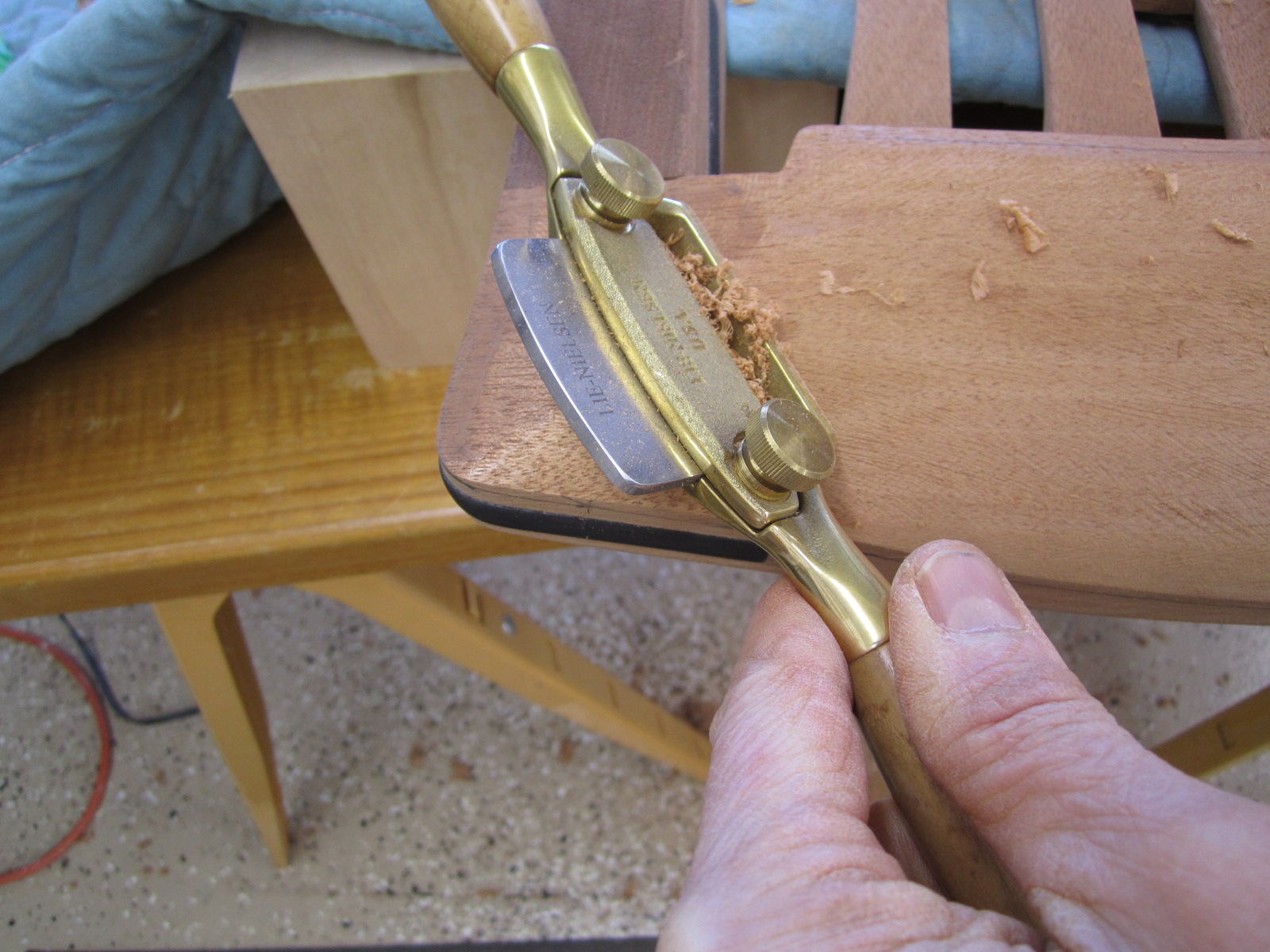
First thing is to round off the corners and do final shaping of the sides. I simply used a rasp and file for this:

Ok, now the challenge - splines! I thought long and hard on using a router. But using a router presented a number of challenges:
1) The ends of the crest rail and the sides of the rear posts are at a diagonal to their front faces. Running a router with a bearing would result in the bearing edge running against the wood rather than the bearing face. The bearing edge will leave a nasty groove along the length of the cut. I tested this before doing the splines on the front of the arms (which are parallelograms). To deal with this bearing groove, final shaping would have to be done after cutting the spline. I've already done final shaping at this point so I would be left with the bearing groove to contend with.
2) Because I shaped the back of the crest rail there was very little wood back there! Also, the cutter cannot simply plunge perpendicular to the top of the crest rail - doing so would risk having the cutter blast through the back of the crest rail. Remember, the original crest rail curves back quite a bit towards the top.
3) Because the top of the crest rail has a pronounced arc the top spline also needs to follow that arc. On some reproductions of this chair I've noticed that the crest rail has been modified and flattened out without the pronounced arc - which would make cutting the spline with a single router setup much easier. On this chair it is tougher.
I'm sure a router setup could be developed. Most likely 2 setups would have to be used for this chair - one for the side and one for the top. Given that there is so little wood at the rear at this time and given all the various angles and sweeps and the nightmare of a dramatic and massive blowout with a sizable chunk of the crest rail flying off across the room within the blink of an eye - I decided to cut the splines by hand.
I decided to shape the crest rail before chopping the splines - not final shaping but close. I'll leave the tops a little thick and I'll shape and blend the transitions later after installing the spline. I do not have a hand held grinder. However, I think my Barr scorp works just as fast (awesome tool!):

After some rasp work, here is what I've got - ready for laying out the splines:

Here are the splines laid out - you can also see that there is not much meat in the rear. (Next time, I think I will leave a bit of waste wood at the rear edges to make this process less precarious - which can still be removed after glue-up.)

The splines are about a 1/4 wide - 2.5 inches long on top and 5 inches long on the side.
I will use 2 setups - one for the top and one for the bottom. I will use the back of the crest rail as my reference edge for the top and the front of the crest rail as my reference edge for the side (although I changed my mine later for the side as we shall see).
I used a marking gauge to mark an undersize groove about 3/16" wide for chopping the top- undersized so that while chopping I do not need to worry about dinging the edges a bit. I also left the MDF clamped to the back to protect the back during chopping to avoid blowout.


Ok, for the sides I was going to use a marking gauge using the front as my reference edge. I changed my mind and decided to use a scribing jig similar to the one I used successfully awhile back when laying out the mortises for the 8 splat dividers (doohickees I called them). The reason for this is that my front post curves back and is not flat. I could have used a flat piece of MDF shimmed here and there to act as a reference edge. But I decided to try this jig using a marking knife rather than a marking gauge:

I laid out an undersized 3/16" groove for rough chopping. Here is what it looks like after chopping:

Next I repeated the layout on top using the marking gauge to slice the final edge and width. I used a sharp chisel to cleanly pair the sides being careful not to ding the final edge:


WARNING! Note that when scribing with a marking knife or gauge one still needs to follow the grain direction (slicing downhill). Doing otherwise can still result in tear out. In the photo above showing the marking gauge I am working the front side of the mortise. You can see that the grain is at a diagonal going from front to back as it approaches the end of the crest rai - so I will be pulling the marking gauge towards me in the photo.
One also needs to follow the grain direction with the pairing chisel. I don't simply pair straight down. I slice at a very slight diagonal then rotate the chisel downhill to the grain. If I slice uphill into the grain the slice may continue and split wood past my marking line - not good! By slicing downhill to the grain the waste piece simply pairs away. In the photo above I am pairing the backside of the mortise. The grain is still flowing at a diagonal from front to back towards the edge - so I am pairing downhill to the grain by pairing away from me.
Hopefully the photos will help make sense - but following grain direction is vital to get good results with either power or hand tools.
Next I sliced the final edges on the side using a different and slightly wider jig. While the top is a 1/4" wide, because the rear post is a parallelogram and diagonal to front of the chair the final width is slightly wider than 1/4". I made the jig wide enough to accurately meet the top groove (about 1/32" wider as it turns out). Once again, I used a marking knife to slice the edge and a sharp chisel to pair the sides:


WARNING! The end grain of the crest rail is very fragile, especially at the top corner. I found this out while chopping, and came dangerously close to blowing out too much material. On final pairing I was very slow and cautious, just nibbling the edges at the corner so the side and top grooves correctly met.
Ok - the jig I used to layout the side groove sounded great in theory. It worked well for the small mortises on the splats. But it did not work too well here. The reason is that the crest rail bends and twists. Clamping the jig to the side resulted in the jig twisting with the crest rail, resulting in a twisted groove. Here is a shot with a test spline. You can see the nice gap at the bottom:

As I mature as a woodworker, I've learned to realize that the craft of woodworking consists a lot of knowing how to fix mistakes. After some pondering, I cut the test spline roughly in half and then tried the fit:

Hey, that works pretty well! Unfortunately, this adds another splice that I will need to fuss with, and there are still one or two very minor gaps - but those gaps can easily be disguised with a bit of sawdust and glue during glue-up. I'll make sure the splice does not line up where the crest rail meets the rear post for strength at that point.
Ok, time to cut ebony. I used a bandsaw and my Jet 10-20 Plus drum sander to shape the ebony splines. I fitted the top and bottom pieces fast - I had to fuss with the middle one quite a bit to make it join with the top and bottom pieces (especially at the top with the compound angles):


After gluing in the splines, I used a dremel with a coarse sanding drum to hog off most of the material:

Then I used a handplane on top, a spokeshave with a curved sole for the side, and a fine file for the corner. The splines are slightly proud. I used sandpaper to ease the edges and give the spline a pillow effect:

Although ebony shapes nicely, one needs to be careful following grain direction to avoid tear out when using edge tools. Here are the splines finished. Cutting these splines was slow going - but I am very pleased with the results. The various splices in the spline are nice and tight and hardly noticeable:

Now time for final shaping of the crest rail. I sanded the back and rounded off the back corner:

The top of the crest rail converges toward the center. I used a draw knife to quickly remove some material then grabbed the rasp, file, and spokeshave to blend and work the transitions:

The photo below shows how the bottom of the crest rail flattens out to meet the rear posts. Once again, I think on the original chair the crest rail has a nice bottom arc and the rear posts twist inward to meet that arc. I look forward to seeing the original, but I do not think my version looks too bad - better than I thought it would.

I still need to do some more sanding and round over some of the edges and corners. Green and Green furniture do not have sharp edges. In the photo below there is a subtle but very important detail. The width of the side crest rail is not a single width. The side tapers and narrows as it approaches the top - so that there is not a whole lot of wood around the ebony spline near the top. I removed wood on both the front and back to taper the sides as it approaches the top. Once I fully round over the edges that detail will become more pronounced.


I will sand the entire chair through the grits up to 220 before installing plugs. I do not want to be sanding around plugs. If I need to sand after that it will be only to touch up.
If I build this chair again I may try to use a router to cut the splines. However, I would definitely make mockup pieces using poplar to fully test the router setups before approaching the real thing. Also, as I mentioned in the past, I would finish the entire back of the chair before gluing on the seat rails and arms - to make the possibility of using a router much easier. Even then, for a single chair, I think a router setup will entail just as much work as cutting the splines by hand.