Pages

Thursday, November 14, 2013

Greene & Greene Blacker House Office Chair - Part IV

"AUTOINTOXICATION"  - The state of eating too much Halloween candy.

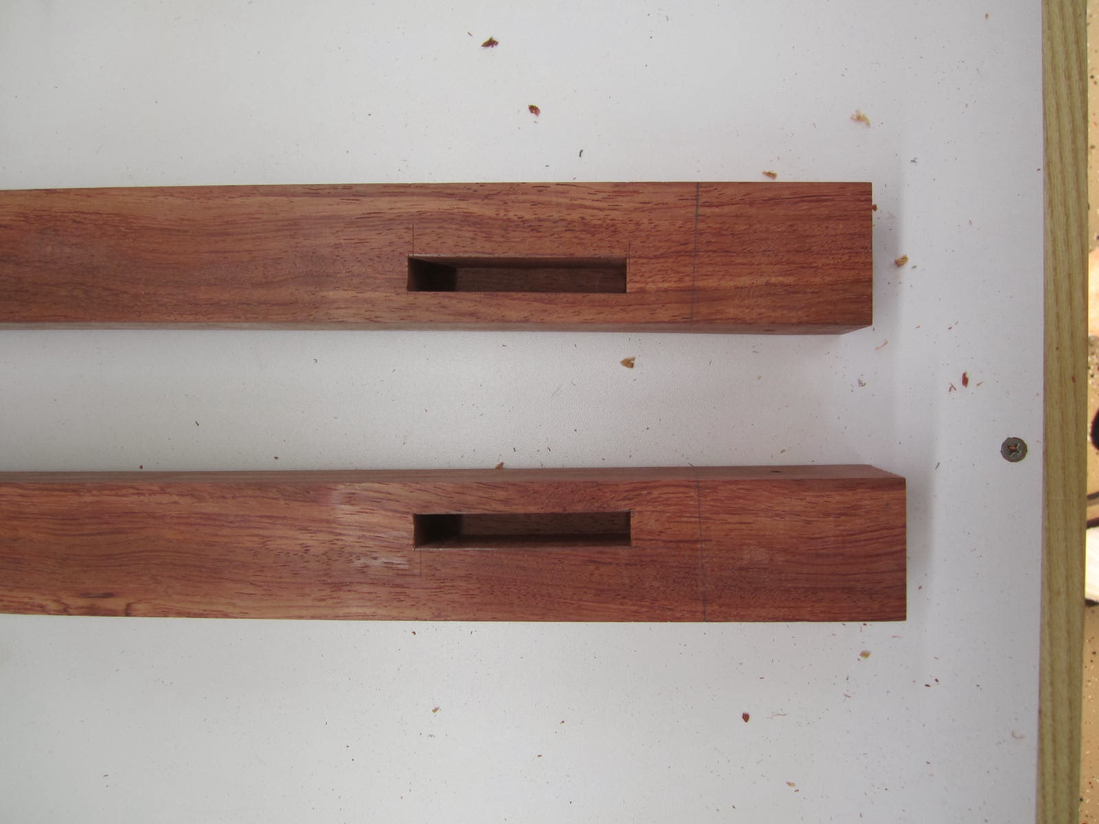
Rails:  The joinery for the back rail is straight forward.  Here is the rail cut to length with the tenon locations penciled at the end (they are 1/2" thick and 5/8" long tenons):


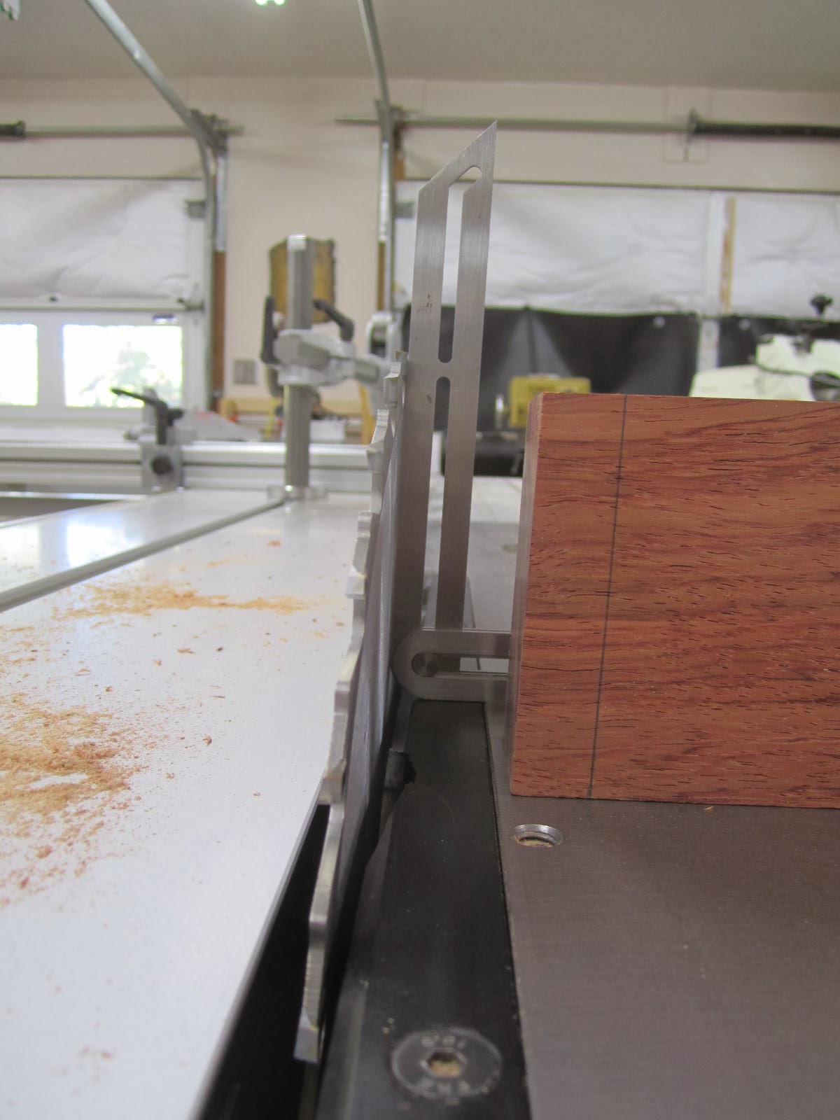
The ruler above shows the cant angle for the rear posts - about 2 degrees.  Now, that cant angle is important for when I cut the side rail tenons.  At this time I will rip a thick piece of scrap wood with one side cut at the same cant angle.  Below is a shot of the rear rail next to the saw blade angled with the cant angle.

Below is the end view of the scrap wood ripped with one side cut at the cant angle:


Now, this scrap wood was milled to the same width as the side rails.  We will come back to this scrap wood shortly.   We will be using it to cut the tenons for the side rails.

However, back to the rear rail.  I did not take any photos cutting the rear rail tenons.  In a nutshell, I used the multi-router.  I also used the multi-router to cut the 1/4" mortises for the plethora of splats.  Then I took the rear rail to the bandsaw and cut the back decorative profile followed with a file, shoulder plane, and sand paper for cleanup:


Now to the side rails.  These will be more complicated!  The side rails will have a compound angled tenon in the back and angled box joints up front.  The tenons will be compound angled because the side rails splay outward and the rear posts have that 2 degree cant angle as well.
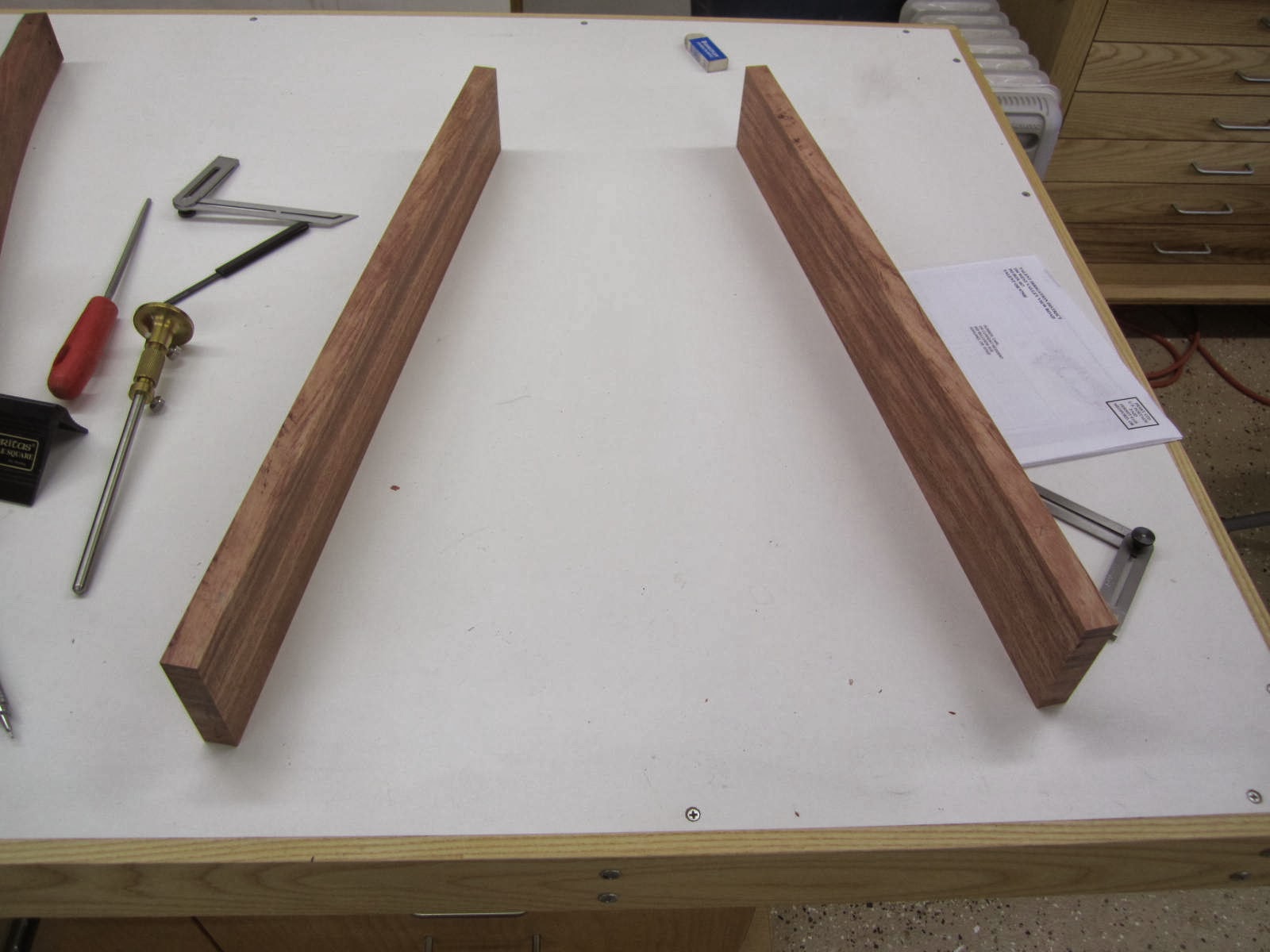

Using my drawing, I determine the splay angle and the corresponding angle required to cut the end of the front rail:


I cut the rails to length with the front angled:


Ok, here comes the tricky part.  The tenons in the rear of the side rails must be accurately laid out!  To lay out compound angle tenons it is important to start at the top shoulder and work around.  For straight tenons we normally layout the tenons at the end of the rail.  But for angled tenons we start at the top shoulder.


From there I mark out the end of the tenon using a bevel gauge adjusted to the cant angle, careful to distinguish left vs right rail:


Then I mark out the bottom of the tenon:


Now, do you remember that scrap piece of wood we ripped earlier that is the same width as the rails with one side cut to the cant angle?  Now is the time to use it:


In the photo above we see the rail on top of the scrap wood.  I glued on 1/4" plywood to the sides.  The side that was ripped at the cant angle is facing down (important!).  What that scrap wood does is tilt the side rail so that the angled tenon is no longer angled but rather parallel to the table surface (or what ever surface - such as a table saw fence).  Also note that to cut the other rail one will use the other side of this scrap wood so the angle is reversed for the other rail's tenon.


Now I take the whole assembly to the multi-router.  The multi-router table is tilted to the splay angle of the rear rails which defines the second angle of the compound angled tenon.  Note that one could use a table saw or bandsaw here with an angled blade and ride the assembly against the fence


Now, before cutting the real tenons, I used a test piece to set my mulit-router end stops for the tenon thickness.  I first cut the whole tenon to 3/8" thickness and test the fit in a scrap piece with a 3/8" thick mortise.


Then I define the two 1/4" through tenons and then test that fit in a mortise that has both the 3/8" thick part and 1/4" part:
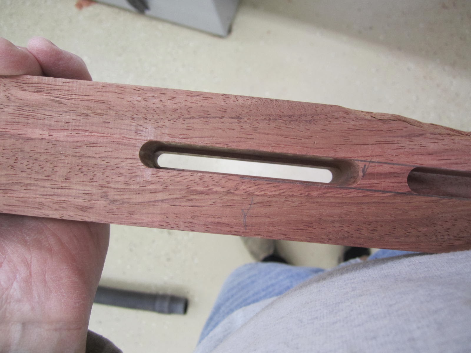


Once I'm satisfied I cut the real McCoy.  Since I will be inserting wedges into the through tenons I need to taper the end of the mortises in the rear post.  I usually go out 1/16".  That is the gap you see above and below the through tenons in the photo below.


Here is the chair assembly dry fitted (note that the rear posts appear heavily angled but this is due to the wide angled camera lens):


Now, for the front rail, we first must determine the length:


The box joint ends will stick out about an 1/8".  I layout the box joints on the side rails and front rail using a caliper:


When cutting the box joints I did not use a box joint jig. I simply cut the side rail box joints to the pencil line then cut the front rail box joints using trial and error with a test piece for fitting.  I used the multi-router since I had the table all set up with the proper splay angle for when I had cut the tenons earlier.  The router bit also left a very nice bottom.  A dado blade would suffice but dado blades tend to leave rabbit ears.  (One of these days I'd like to get a box joint cutting blade with a flat top).

I got all the joints fitting well except for one (there is always that one!).  I glued on a shim and tried once more:


I then beveled the ends of the box joints.  I used a file. One thing to note about this piece.  Traditional Greene & Greene furniture uses a lot of heavy round overs.  I am breaking from tradition here using very light round overs and beveled edges.  Just for the hell of it.


Good time to call it quits.  Now, where did my wife hide the Halloween candy...

Friday, November 1, 2013

Greene & Greene Blacker House Office Chair - Part III

I was talking to a master craftsman the other day who is also a fellow member of the Siskiyou Woodcraft Guild here in southern Oregon.  He mentioned that the industry standard for the slope of the seat (towards the rear of course) is about 6 degrees while the rear posts are usually 90 degrees to the side rails.  Consequently, the rear posts start off with a 6 degree angle.  Now, this fellow's dining chair seats have a 4 degree slope.  Then the rear posts are angled another 2 degrees back with respect to the side rails.  Consequently, the rear posts start off with the same 6 degree angle as the industry standard.  There are certainly opportunities to experiment with the angles here.  A 6 degree or higher seat slope is probably more for lounging.  At a dining table one wants to be more upright.  Once the ole tummy is full and gravity takes hold then leaning back those 2 degrees can make a difference in comfort - and his chairs are extremely comfortable.

The swivel office chair I am working on will have a 3 degree seat slope, as dictated by the swivel hardware underneath (of course, I could add shims here and there to modify that angle but I decided to stay with the hardware setting).  Also, the rear posts are 90 degrees to the side rails.  Consequently, the rear posts will have a starting angle of 3 degrees rather than the industry norm of 6.  This will be OK since the hardware allows the chair to lean back.  Otherwise, one wants a good upright position for good posture at a desk.

While the rear posts are 90 degrees to the side rails, they have about a 2 degree cant angle vis-a-vis the rear rail.  2 degrees doesn't seem like much but visually it is a very nice angle.  Another very important thing is that the rear posts were rough cut from the lumber in such a way that the grain will flow up and out.  We certainly do not want the rear posts to angle outward but then have the grain flow inward!

Here are the rear posts rough cut, front facing up.  We are looking at the edge of the 8/4 lumber.  They are labeled left and right.  Although it is difficult to tell in this photo, the grain direction is definitely flowing in the direction I want:


Below we see that I have VERY LITTLE wiggle room to extract the front profile from the 8/4 edge - so I have to be careful here!


I've got 2 templates - one for the side profile and one for the front profile.  I'll work on the side profile first.  Because I have so little wiggle room with the thickness of the lumber, I start by hand planing the inside surface taking very little off (the jointer takes too much off).   With a somewhat flat inside surface I then surface the front of the post on the jointer so that it is 90 degrees to the inside surface.  I follow with a hand plane.  I lay the post on its side (inside surface down) and screw on the template.


Note that the critical area at the bottom of the template is perfectly flush with the flat hand planed front edge - this is a reference edge where the side rails will later meet the rear posts.  After removing waste on the bandsaw I take the assembly to the shaper.  The nice thing about the shaper is that I can reverse the cutter and the cutting direction to follow the grain without removing the template (as one would have to do on a router table).


I do not let the shaper cutter touch the hand planed reference edge at the bottom that is flush with the template.  After shaping the front I then shape the rear.  Also, I mark on the wood the location of the eventual post bottom.

Now its time to shape the front profile.  In order to fit the front template I need to shift the template at an angle.  I also make sure the location of the post bottom on the template is inline with the mark on the post.


I use the router table here. The cutting action is pretty much down hill for both sides.   Because the post now has a taper so to speak I have to shape the post in increments - lowering the bit each time.  This was somewhat tedious and dangerous.  If the bearing lost contact with the template then who knows what could happen to the post!  To be honest, I think I could have simply bandsawn the profile then gone straight to hand tools.  However, the router cut made hand tooling easier.

Once shaped I then revisit the inside reference edge to make sure that it is flat and 90 degrees to the front reference edge.  If you recall, the front reference edge was hand planed earlier and is ready for joinery.


Note the beautiful Marcou S20 smoother.  I bought this years ago when I was still earning money in the corporate world.  (I couldn't afford it now!).  It is a "low angle" handplane with a 20 degree bed rather than the typical 12 degree bed.  It also uses standard Veritas blades.  I am using a blade with a 40 degree angle for a 60 degree cutting angle - necessary for this tough and somewhat curly lumber.  Absolutely no tear out.

Next I use a file to remove the shaper marks.  The file leaves a nice surface which can be sanded with minimal effort.


With the lower reference edges good to go (where the posts meet the side and rear rails) I now need to check the third and final reference edge - where the post meets the crest rail.  That reference edge needs to be flat across both posts, and it needs to be co-planar with respect to the bottom of the post.  For what ever reason, I am not flush here.  I may have gotten overly exuberant with the file, or during the process of truing the inside reference edge earlier I got the top out of whack.  I do notice that I am too thick here to begin with.


Ok, now this looks much better.  I also use winding sticks to check the co-planar question vis-a-vis the bottom of the post.  Note that my block plane above is configured with a 50 degree blade for an effective 62 degree cutting angle.  A sharp blade and a waxed plane bottom keeps exertion to a minimum.


Now, I mortise the inside face for the rear rail tenon.  Straight forward.


However, cutting the mortise on the front face for the side rail is a bit more complicated.  Michael Fortune wrote an article in Fine Woodworking  (July/August 2012) called "A Revolution in Chairmaking" which describes, among other things, the use of a stepped tenon for where the side rail connects to the rear post.  I think it is an awesome tenon.  I used it for a settee I built earlier in the year.  For this swivel chair, where the rear posts quit just below the seat, I think a lot more stress is placed on this section than if the chair had full rear posts that met the floor.  Consequently, this type of tenon joint is even more appreciated here.  Michael describes cutting this joint using a router and a shop made router jig.  I encourage you to read that article.  I am using a multi-router but the principle is pretty much the same.

I'll jump ahead briefly to show you the finished result.  Note that the small through tenons will each have 2 wedges (I have yet to cut the wedge kerfs in the photo below).  Rather than have one large tenon slicing through the post, the two smaller tenons requires the removal of far less post material, no doubt resulting in a stronger post.  But with 4 wedges rather than 2 the tenon is at least as strong if not stronger than using a single through tenon.


First I use a 3/8" end mill bit to cut the main tenon 7/8" deep.  I remove the post and square the edges:


Next, I install a 1/4" cutter on the router.  I use a long upcut spiral bit.  I did not change the height setting of the multi-router.  Consequently, the 1/4" cutter will be exactly centered in the 3/8" mortise.  We will be cutting 2 small mortises through this larger mortise.  For the first mortise, I move the cutter to one end of the mortise and set the stop.  Then I use a 1/16" gauge to move the cutter over 1/16" from the end:


Now, the mortise is 5/8" long.  The cutter is 1/4" wide.  So I need 3/8" of travel on the other end.  I use gauges to set that distance.


Then I set the other stop.  Now have my side to side stops set.  Michael Fortune does pretty much the same thing with his shop made router jig.


Now I cut the mortise.  Because I am using an upcut spiral bit I get no tear out when punching through (and I go slow here!)


I perform the same steps starting from the other end of the primary mortise to cut the second small mortise:


Later I square the ends of the small mortises and add a taper (about a 1/16" flare) to accept a wedged tenon.

While I could cut the posts to length, I've decide to hold off.  Having extra meat at each end may facilitate clamping later on.

Time to call it quits!